Barrier Assembly Instructions |
||||||||||||||||||||||||||||||||||||||||||||||||||||||||||||||||||||||||||||||||||||||||||||||||||||||||||||||||||||||||||||||||||
|
|
||||||||||||||||||||||||||||||||||||||||||||||||||||||||||||||||||||||||||||||||||||||||||||||||||||||||||||||||||||||||||||||||||
 |
||||||||||||||||||||||||||||||||||||||||||||||||||||||||||||||||||||||||||||||||||||||||||||||||||||||||||||||||||||||||||||||||||
|
||||||||||||||||||||||||||||||||||||||||||||||||||||||||||||||||||||||||||||||||||||||||||||||||||||||||||||||||||||||||||||||||||
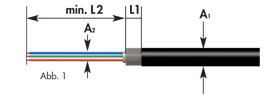 |
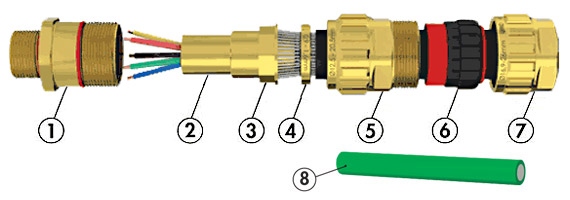
Step 1 The cable is to be prepared as shown in Fig. 1. For L1 dimension see table. Choose measurement L2 depending on the installation. The inner cable jacket (A2) must be free of damage and should extend beyond the cable gland. Important: The Exios Barrier Cable Gland is typically designed for use with armored cables. However it is also possible and permitted to use with NON-ARMORED cables. In this case it is important to use one clamping ring as a spacer for the installation! |
|||||||||||||||||||||||||||||||||||||||||||||||||||||||||||||||||||||||||||||||||||||||||||||||||||||||||||||||||||||||||||||||||
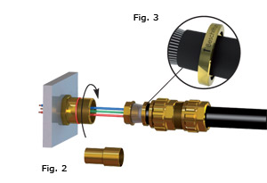 |
Step 2 The cable gland is delivered with 2 armor clamping rings. Choose the appropriate clamping ring (measure armor thickness and see Table 1); the other ring can be discarded. Follow the installation instructions shown in Fig. 2. Pay attention to the correct installation of the clamping ring, Fig. 3. The arrow on the clamping ring should point towards the installation. Step 3 Install the entry component on the device or housing (∼15Nm / 11.6 foot pounds). The end-user is responsible for ensuring that, at the point of installation, the adapter for the entry component has been made ready in accordance with Regulations. The entry component can be provided with a locknut to keep it from working loose. |
|||||||||||||||||||||||||||||||||||||||||||||||||||||||||||||||||||||||||||||||||||||||||||||||||||||||||||||||||||||||||||||||||
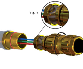 |
Step 4 Position the armour of the cable so that all parts of the armor are in contact with the armor cone (Fig. 4) and the ends of the armor touch the edge of the armor cone. Now screw the gland body hand-tight onto the entry component. It helps if, while doing so the cable is pushed slightly in towards the device or housing. With the appropriate open-ended spanner (tool), tighten fast in order to securely clamp the armor. |
|||||||||||||||||||||||||||||||||||||||||||||||||||||||||||||||||||||||||||||||||||||||||||||||||||||||||||||||||||||||||||||||||
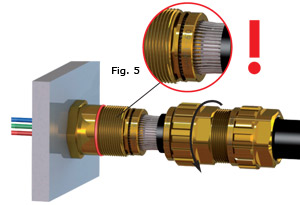 |
Step 5 Loosen the gland body and check for correct seating of the armor (Fig. 5). The armor must be firmly clamped. If need be, repeat step 4. |
|||||||||||||||||||||||||||||||||||||||||||||||||||||||||||||||||||||||||||||||||||||||||||||||||||||||||||||||||||||||||||||||||
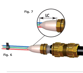 |
Step 6 Mix and knead the appropriate quantity of compound for the job until a completely uniform color is achieved. As shown in Fig. 6, apply the compound between and around the individual conductors. To prepare for the sleeve (cover) it is easy if the compound has first been giving a conical shape as in Fig. 7. To stop the conductors moving out of place, they can be held together with scotch tape. |
|||||||||||||||||||||||||||||||||||||||||||||||||||||||||||||||||||||||||||||||||||||||||||||||||||||||||||||||||||||||||||||||||
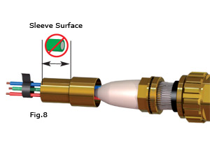 |
Step 7 Push sleeve over compound portion behind armor cone. This causes the compound to be compressed. Remove the excess compound. Care should be taken that sleeve has been filled right up to the end. The outside of the sleeve is to be kept clean. |
|||||||||||||||||||||||||||||||||||||||||||||||||||||||||||||||||||||||||||||||||||||||||||||||||||||||||||||||||||||||||||||||||
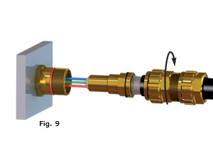 |
Step 8 The cable can now be inserted into the entry component. The sleeve should be inserted carefully. |
|||||||||||||||||||||||||||||||||||||||||||||||||||||||||||||||||||||||||||||||||||||||||||||||||||||||||||||||||||||||||||||||||
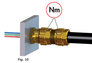 |
Step 9 After the entry component and the gland body have been screwed together again (Step 4, Nm), the dome nut can now be tightened. To speed up assembly, it can be tightened by hand to start with. Then tighten down using an open-ended spanner (Nm). |
|||||||||||||||||||||||||||||||||||||||||||||||||||||||||||||||||||||||||||||||||||||||||||||||||||||||||||||||||||||||||||||||||
|
||||||||||||||||||||||||||||||||||||||||||||||||||||||||||||||||||||||||||||||||||||||||||||||||||||||||||||||||||||||||||||||||||
General information:
|
||||||||||||||||||||||||||||||||||||||||||||||||||||||||||||||||||||||||||||||||||||||||||||||||||||||||||||||||||||||||||||||||||