Assembly Instructions
|
 PDF Assembly Instructions PDF Assembly Instructions |

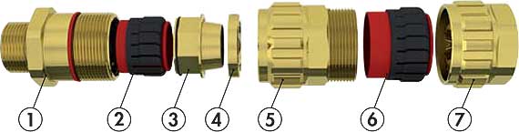 |
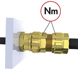
Components:
1. Entry Component
2. Inner Jacket Sealing
3. Interlocking Armor Cone
4. Armor Clamping Ring
5. Gland Body
6. Outer Jacket Sealing
7. Dome Nut |
Certification Details:
Cable Gland Type: EXIOS
II 2G Ex de IIC Gb / II 1D Ex ta IIIC Da
IECEx: Nr. BVS 10.0078X
ATEX: Nr. BVS 10 ATEX E062X
EN/IEC 60079-0/2009
EN/IEC 60079-1/2007
EN/IEC 60079-7/2007
EN/IEC 60079-31/2009
EN 60529 |
|
 |
Step 1
The Cable Gland is to be prepared as shown in Fig. 1. For L1 dimension see table. Choose measurement L2 depending on the installation. The inner cable jacket (A2) must be free of damage and should extend beyond the cable gland. |
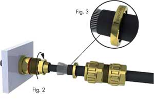 |
Step 2
The cable gland is delivered with 2 armor clamping rings. Choose the appropriate clamping ring (measure armor thickness and see Table 1); the other ring can be discarded. Follow the installation instructions shown in Fig. 2. Pay attention to the correct installation of the clamping ring, Fig. 3. The arrow on the clamping ring should point towards the installation.
Step 3
Install the entry component on the device or housing (∼15Nm / 11.06 foot pounds)). The end-user is responsible for ensuring that at the point of installation, the adapter for the entry component complies to regulations. The entry component can be provided with a locknut to keep it from turning loose. |
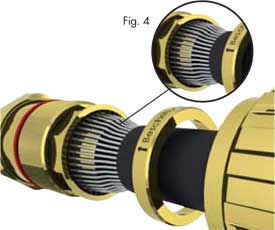 |
Step 4
Position the armor of the cable so that all parts of the armor are in contact with the armor cone (Fig. 4) and the ends of the armor touch the edge of the armor cone.
Screw the gland body hand-tight onto the entry component. While doing so, it helps if the cable is pushed slightly in towards the device or housing. With the appropriate open-ended wrench (tool), tighten in order to securely clamp the armor.
|
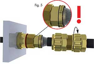 |
Step 5
Loosen the gland body and check for correct positioning of the armor (Fig. 5). The armor must be firmly clamped. If need be, repeat step 4. |
 |
Step 6
After the entry component and the gland body have been screwed down again (Step 4, Nm), the dome nut can now be tightened. To speed up assembly, it can be tightened by hand to start with. Then tighten down using an open-ended wrench (Nm). |
| Size |
Thread |
Wrench
Flat |
Ø A1 |
Ø A2 |
Armor Acceptance Range |
L1 |
PF |
| Metric |
NPT |
Ring 1 |
Ring 2 |
Ring 3
(optional) |
| 20-1 |
M16 |
3/8" |
.87"(22) |
.24 - .47"
(6-12) |
.12 - .32"
(3-8.1) |
0-0.03"
(0-0.7) |
0.03-0.05"
(0.7-1.25) |
– |
.79"
(20) |
11.06 |
| M20 |
| 20-2 |
M20 |
1/2" |
.94"(24) |
.35 - .63"
(9-16) |
.24 - .47"
(6-12) |
0-0.03"
(0-0.7) |
0.03-0.05"
(0.7-1.25) |
– |
.79"
(20) |
12.54 |
| 20-3 |
M20 |
1/2" |
1.18"(30) |
.49 - .81"
(12.5-20.5) |
.35 - .55"
(9-14) |
0-0.03"
(0-0.7) |
0.03-0.06"
(0.7-1.4) |
– |
.79"
(20) |
14.75 |
| M25 |
| 25 |
M25 |
3/4" |
1.42"(36) |
.67 - 1.02"
(16.9-26) |
.49 - .81"
(12.5-20.5) |
0-0.03"
(0-0.7) |
0.04-0.06"
(0.9-1.6) |
0.03-0.06"
(0.7-1.4) |
.79"
(20) |
25.81 |
| 32 |
M32 |
1" |
1.81"(46) |
.87 - 1.30"
(22-33) |
.67 - 1.02"
(16.9-26) |
0-0.03"
(0-0.7) |
0.05-0.08"
(1.3-2.0) |
0.03-0.06"
(0.7-1.4) |
1.18"
(30) |
44.25 |
| 40 |
M40 |
1-1/4" |
2.17"(55) |
1.10 - 1.61"
(28-41) |
.87 - 1.30"
(22-33) |
0-0.03"
(0-0.7) |
0.05-0.08"
(1.3-2.0) |
0.03-0.06"
(0.7-1.4) |
1.18"
(30) |
59.00 |
| 1-1/2" |
| 50 |
M50 |
2" |
2.56"(65) |
1.42 - 2.07"
(36-52.6) |
1.14 - 1.75"
(28.9-44.4) |
0-0.04"
(0-1.0) |
0.06-0.10"
(1.5-2.5) |
0.04-0.08"
(1.0-2.0) |
1.38"
(35) |
53.10 |
| 63 |
M63 |
2-1/2" |
3.15"(80) |
1.81 - 2.57"
(46-56.3) |
1.57 - 2.22"
(39.9-56.3) |
0-0.04"
(0-1.0) |
0.06-0.10"
(1.5-2.5) |
0.04-0.08"
(1.0-2.0) |
1.57"
(40) |
59.00 |
| 75 |
M75 |
3" |
3.74"(95) |
2.24 - 3.07"
(57-78) |
1.99 - 2.69"
(50.5-68.2) |
0-0.04"
(0-1.0) |
0.06-0.10"
(1.5-2.5) |
0.04-0.08"
(1.0-2.0) |
1.77"
(45) |
110.63 |
| Dimensions in Inches (mm) |
|
General information:
- Our metric-size cable glands are provided as standard with an O-ring on the connecting thread.
- Before initial operation of the facilities, the assembly is to be checked to see that it conforms to these installation instructions, to the applicable national and international standards, as well as those applicable to the use in question.
- Suitable tools must be used for the assembly; furthermore, the installation may only be carried out by qualified electricians or by trained staff.
- Any modification which differs from the condition as delivered is not permitted.
- In order to fulfill explosion protection type Ex-d, the cable used must be round and compact (cf. IEC 60079-14 Para. 10.2). The cables must also take into consideration in particular the Regulations as per EN 60079-14 Section 9.5.2. Observe the Regulations of EN 60079-14 on direct insertion into the Ex-d area.
- At the specified maintenance intervals it is recommended to check the compression fittings and tighten as necessary.
- The use of cables without armor or alternatively the use of cables with shielding braid is only permitted for permanently installed power lines (25%).
- In the case of NPT connecting threads, the end-user must ensure that the necessary IP protection is guaranteed; this can be done using a suitable thread sealing agent.
- When installing the cable gland through knockouts, care should be taken that the maximum diameters are not exceeded.
- The cable glands are provided with a sealing ring with an axial sealing height of at least 5 mm. With reference to the clearance groove, the end-user should ensure that at least five complete turns of the connector thread are made. In order to guarantee a screw depth of 8 mm, the enclosure should have a wall thickness of min. 10 mm ; if <10 mm, then if necessary, use a washer when cable entries are attached to the pressure-resistant enclosure.
- When determining the temperature ranges of the device in the dust Ex-area, the Regulations of EN 60079-0 and EN 60079-31 must be taken into consideration.
|